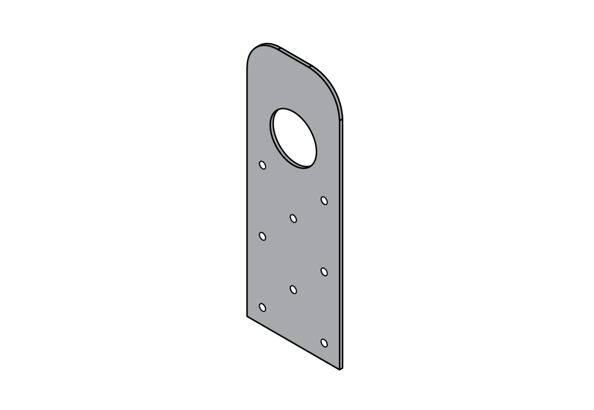
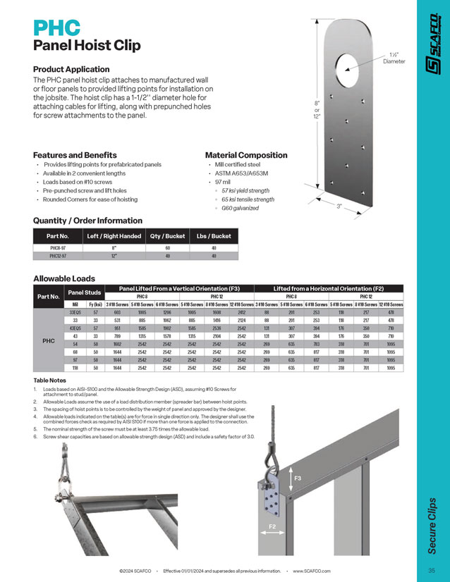
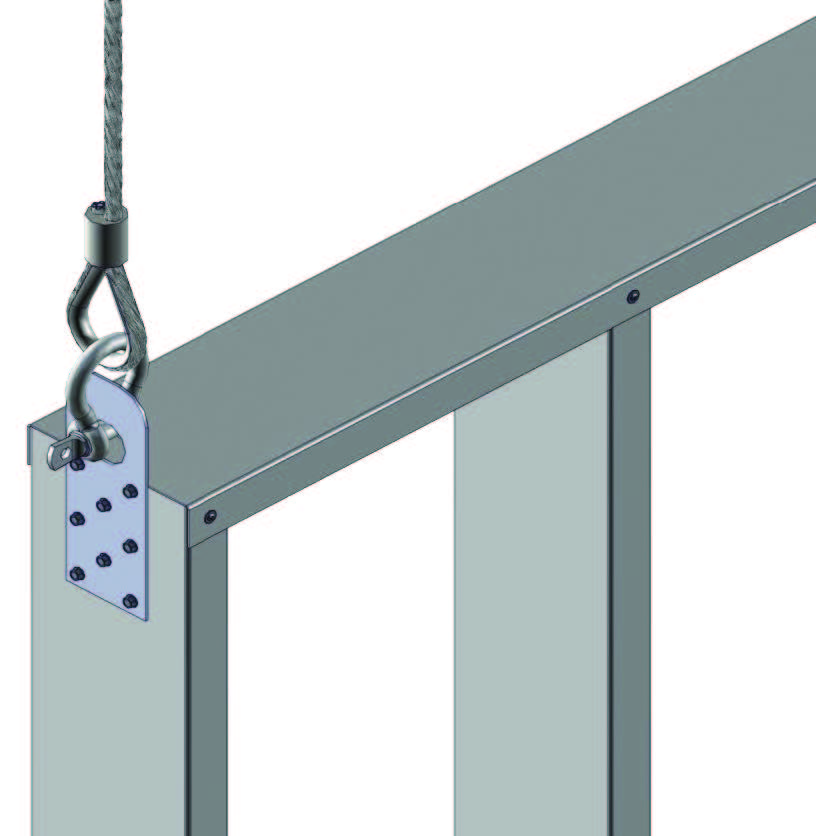
The PHC panel hoist clip attaches to manufactured wall
or floor panels to provided lifting points for installation on
the jobsite. The hoist clip has a 1-1/2” diameter hole for
attaching cables for lifting, along with prepunched holes
for screw attachments to the panel.
Features and Benefits
- Provides lifting points for prefabricated panels
- Available in 2 convenient lengths
- Loads based on #10 screws
- Pre-punched screw and lift holes
- Rounded Corners for ease of hoisting
PHC Submittal Download
Material Composition
- Mill certified steel
- ASTM A653/A653M
- 97 mil
– 57 ksi yield strength
– 65 ksi tensile strength
– G60 galvanized coating
| Part No. | Panel Studs | Panel Lifted from a Vertical Orientation (F3) | Panel Lifted from a Horizontal Orientation (F2) | |||||||||||
|---|---|---|---|---|---|---|---|---|---|---|---|---|---|---|
| PHC8 | PHC12 | PHC8 | PHC12 | |||||||||||
| Mils | Fy (ksi) | 3 #10 Screws | 5 #10 Screws | 6 #10 Screws | 5 #10 Screws | 8 #10 Screws | 12 #10 Screws | 3 #10 Screws | 5 #10 Screws | 6 #10 Screws | 5 #10 Screws | 8 #10 Screws | 12 #10 Screws | |
| PHC | 33EQS | 57 | 603 | 1005 | 1206 | 1005 | 1608 | 2412 | 88 | 201 | 253 | 118 | 217 | 478 |
| 33 | 33 | 531 | 885 | 1062 | 885 | 1416 | 2124 | 88 | 201 | 253 | 118 | 217 | 478 | |
| 43EQS | 57 | 951 | 1585 | 1902 | 1585 | 2536 | 2542 | 131 | 307 | 394 | 176 | 350 | 710 | |
| 43 | 33 | 789 | 1315 | 1578 | 1315 | 2104 | 2542 | 131 | 307 | 394 | 176 | 350 | 710 | |
| 54 | 50 | 1602 | 2542 | 2542 | 2542 | 2542 | 2542 | 269 | 635 | 783 | 318 | 701 | 1095 | |
| 68 | 50 | 1644 | 2542 | 2542 | 2542 | 2542 | 2542 | 269 | 635 | 817 | 318 | 701 | 1095 | |
| 97 | 50 | 1644 | 2542 | 2542 | 2542 | 2542 | 2542 | 269 | 635 | 817 | 318 | 701 | 1095 | |
| 118 | 50 | 1644 | 2542 | 2542 | 2542 | 2542 | 2542 | 269 | 635 | 817 | 318 | 701 | 1095 | |
Table notes:
- Loads based on AISI-S100 and the Allowable Strength Design (ASD), assuming #10 Screws for attachment to stud/panel.
- Allowable Loads assume the use of a load distribution member (spreader bar) between hoist points.
- The spacing of hoist points is to be controlled by the weight of the panel and approved by the designer.
- Allowable loads indicated on the table(s) are for force in a single direction only. The designer shall use the combined forces check as required by AISI S100 if more than one force is applied to the connection.
- The nominal strength of the screw must be at least 3.75 times the allowable load.
- Screw shear capacities are based on allowable strength design (ASD) and include a safety factor of 3.0.
Quantity / Order Information
| Part No. | Left/Right Handed |
Qty /Bucket |
Lbs /Bucket |
|---|---|---|---|
| PHC8-97 | 8″ | 60 | 40 |
| PHC12-97 | 12″ | 40 | 40 |