• Skip to primary navigation
  • Skip to main content

SCAFCO Steel Stud Company

Steel Framing Studs and Track

MENUMENU
  • Home
  • Products
    • Steel Framing Studs, Track, and Furring
      • Steel Framing Studs and Track
      • Supreme Framing System
      • Corner Stud
    • Deflection Clips
      • Clip Central
      • PLC4 – Bypass Slab Slide Clip
      • PLC2 – Bypass Slab Slide Clip
      • PLS2 – Bypass Slab Slide Strut
      • DPLC2 – Bypass Slab Drift Clip
      • DPLS2 – Bypass Slab Drift Strut
      • ESC – Exterior Head-of-Wall Deflection Slide Clip
      • DESC – Exterior Head-of-Wall Drift Clip
      • SSWT – Splicing Slide Clip and Rigid Wall Tie
      • STP – Bypass Slab Top Plate
    • Secure Clips
      • Clip Central
      • AC – Bypass Slab Secure Clip
      • AS – Load-Bearing Secure Strut
      • BC – Secure Bridge Clip
      • FA – Secure Floor Anchor Clip
      • HG – Secure Plate Header Gusset
      • MA – Multi-Use Secure Clip
      • MB – Multi-Use Secure Clip
      • MC – Multi-Use Secure Clip
      • PHC – Panel Hoist Clip
    • Backing, Blocking, and Stiffeners
      • WST – Web Stiffener Track
      • KB – Wall Support Backing Kwik-Back
      • TB – Solid Track Blocking
      • FTB – Fire Track Blocking
      • NS – Notched Stud Backing
      • NT – Notched Track Backing
      • Kwik-Bridge Punch System
      • ELEV – Elevator Stud Splice Clip
    • Head-of-Wall Deflection Systems (Slotted)
      • Slotted Track
      • Seismic Drift Track
      • TTDS – Track-in-Track Deflection System
    • I-Stud Shaftwall System
    • Priceless Header and Kwik-Jamb System
    • ‘Perfect Curve’ Curved Products
    • Custom Brake Shapes to 24′
    • Ponywall Support
    • SoundGuard™ Silent Steel Framing System
    • Serenity-RC-Plus
    • Order Forms
    • Quick Bid Database
  • Submittal Builder
  • Catalogs
  • Tech Library
    • Catalogs
    • Material Certification Reports
    • Architectural Spec Review
    • Continuing Education
    • Engineering Services
    • BIM Software
    • Fire & Acoustic Data
    • LEED and Sustainability
    • Buy American and Buy America
    • CFS Design Software
    • Industry References
    • Steel Framing Standards and CAD Details
    • SDS Sheets
    • Galvanized Coatings
  • About
    • Company Profile
    • Charitable Contributions
    • Contact Us
    • Request Information
  • Careers
  • News
  • Search
Home > Products > Backing, Blocking, and Stiffeners > KB – Wall Support Backing Kwik-Back

KB – Wall Support Backing Kwik-Back

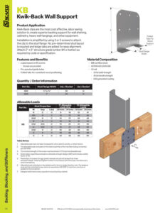
Kwik-Back (KB) products are the most cost effective and labor saving solution for creating superior backing support for wall shelving, cabinetry, heavy wall hangings, and other equipment.

Installation is simplified by using three screws and attaching the clip to the stud flange. No predetermined stud layout is required and ledge tabs are added for easy alignment. Attach 2″ x 6″ structure grade lumber (#1 or better) as required by codes or specifications.
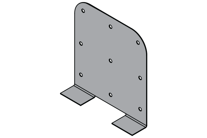
KB Clip

Features

  • Loads based on #8 screws
    • Screws are provided
  • Pre-punched guide holes
  • Folded tabs for consistent wood positioning
thumbnail of KB

KB Submittal Download

Material Composition

  • ASTM A653/A653M
  • Material thickness: 33 mil
  • Yield strength: 33 ksi
  • G60 hot-dipped galvanized coating
KB Clip

Gallery

Allowable Loads

Part No. Stud Properties F1 Allowable Loads (lbs) F3 Allowable Loads (lbs)
Mil Gauge Fy (ksi) 2 #8 Screws 3 #8 Screws 2 #8 Screws 3 #8 Screws
KB 18 25 33 79 118 132 197
20EQ 20 57 114 170 190 285
30EQD 20 57 142 213 266 398
30 20 33 130 196 281 422
33EQS 20 (S) 57 178 267 373 560
33 20 (S) 33 145 217 328 493
43EQS 18 57 242 342 460 689
43 18 33 189 283 460 689
54 16 50 342 342 460 689

Screw shear values are based on the SSMA Screw Table with the following notes:

  1. Allowable loads have not been increased for wind, seismic activity, or other factors.
  2. The allowable loads are based on the steel properties of the members being connected, per AISI S100.
  3. The nominal strength of the screw must be at least 3.75 times the allowable loads.
  4. Values include a 3.0 factor of safety.
  5. Penetration of screws through joined materials should not be less than three exposed threads. Install and tighten screws in accordance with the screw manufacturer’s recommendations.
  6. Allowable loads indicated on the table(s) are for force in single direction only. The designer shall use the combined forces check as required by AISI S100 if more than one force is applied to the connection.

Quantity / Order Information

Model No. Flange Width Qty
/Bucket
Lbs
/Bucket
KB162 1-1/4” to 1-5/8” 200 50
KB200 2″ 200 54
  • Facebook
  • LinkedIn
  • YouTube

About Us • Contact Us • Request Information • Careers

Proposition 65 · CA Transparency In Supply Chains Act · Privacy Policy

Copyright © 2025 · SCAFCO Steel Stud Company · All rights reserved
A subsidiary of the Stone Group of Companies